
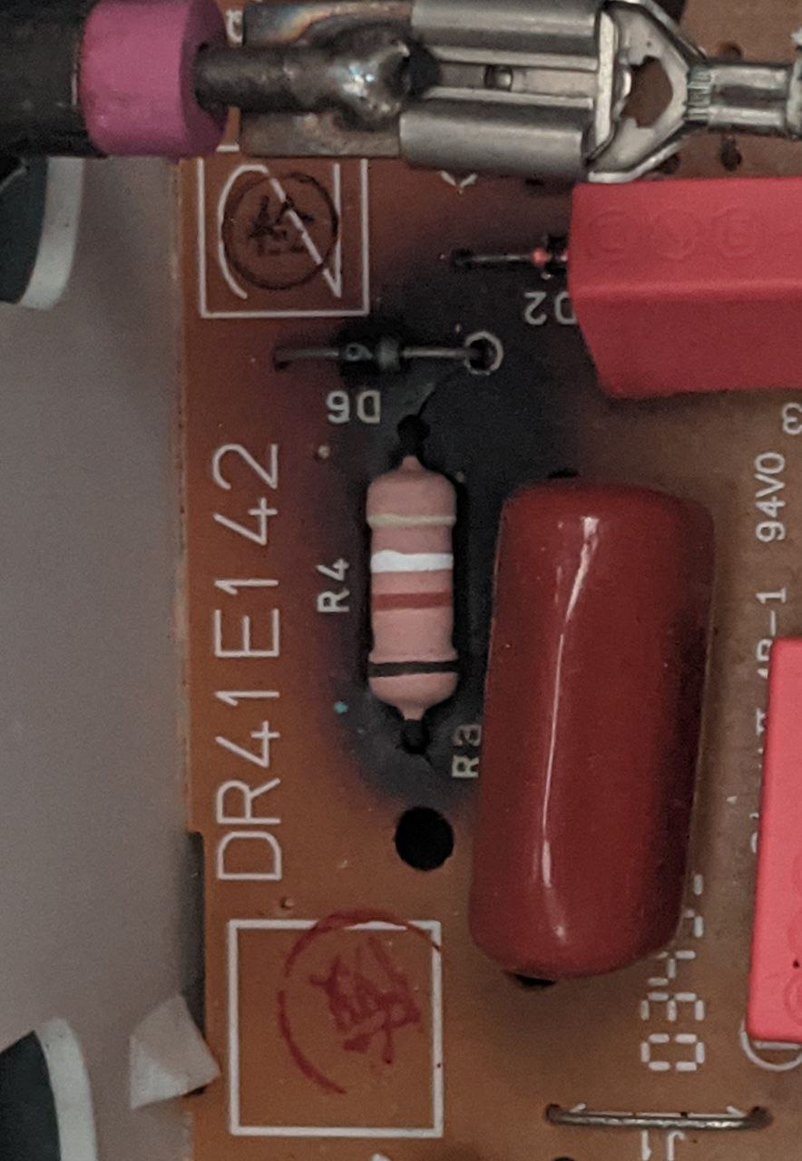
Mates bread maker stopped working so I had a look inside and saw this burned resistor.
I’m guessing the heat changed the colors a bit so wondering if anyone has experience in reading cooked resistor values.
I removed it from the PCB and measured it at 403 Ohms.
Thanks for any help.
It looks like 1GΩ (black-brown-white gold). But that doesn’t sound likely unless you have a very high voltage bread maker.
If we treat the black band as discolored-brown, and read it the other way, we get (yellow - white - brown - brown) which is 490Ω and closer to your measured value. I wouldn’t rule out (yellow - white red - brown) either at 4.9 kΩ, although that doesn’t match closely to your measurement.
A good question is ‘why did the resistor burn?’. If I didn’t know why, then I would assume that replacing it will just result in it burning again, although maybe not immediately.
Thanks! I’ll try replacing it with a 490 ohm resistor and see if it works again.
The element in the bread maker looks like it came loose a bit and made slight contact with the internal metal housing. I wonder if that caused the resistive element to sink more current than the PCB was designed for, burning out the resistor.
That sounds like a possible fail state. Also shitty design. It should use a resettable thermal fuse or something to detect faults without parts burning.
Consider maybe adding a fuse to the design?
Success!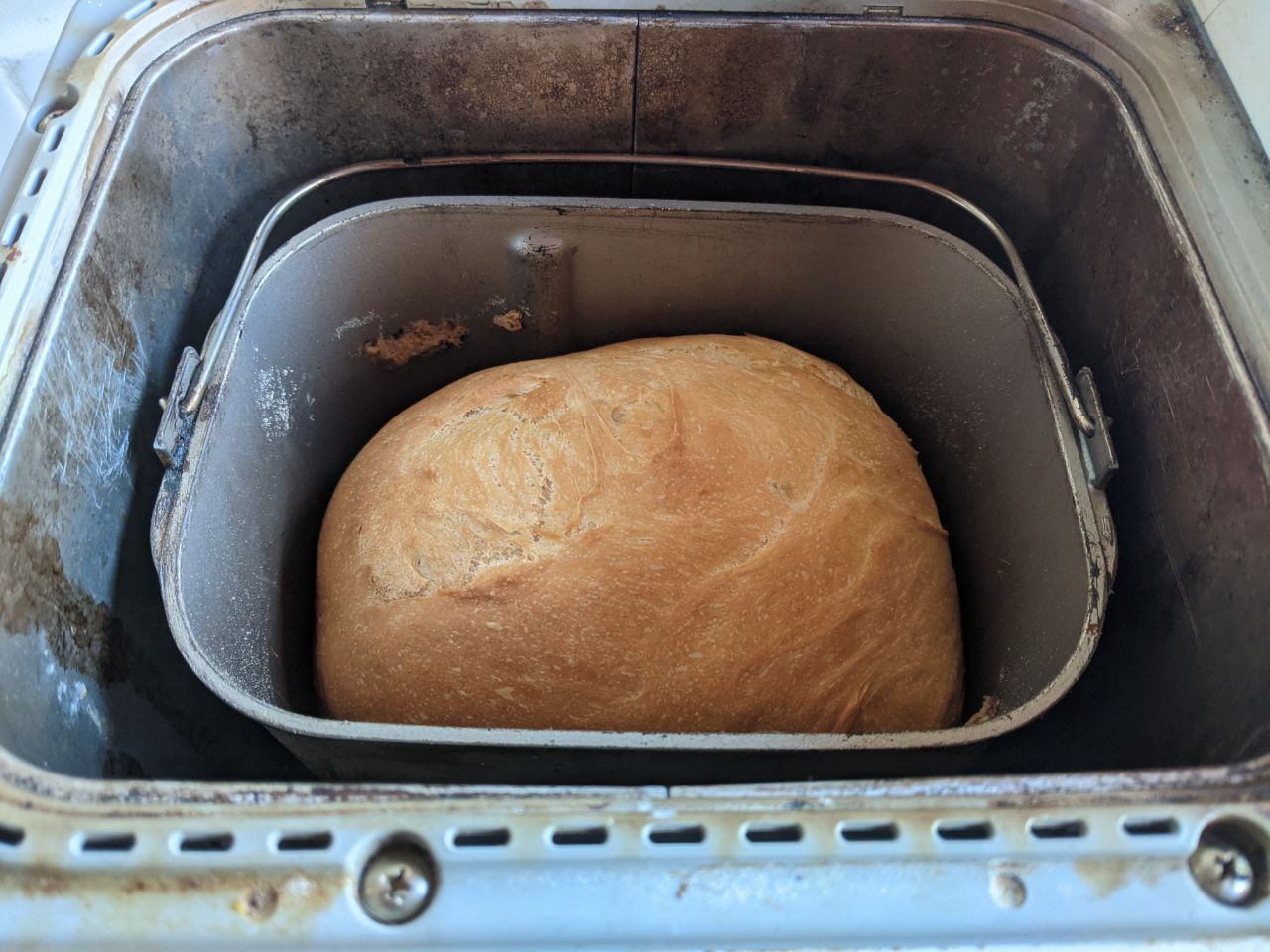
Isn’t it safer/better to start by replacing and testing with a higher resistor? Or is my thinking too simple?
Well, arguably keeping the resistor the same value would result in a somewhat known state, and changing it would put it in an unknown state. The unknown state could be better or worse. I can’t see enough to know what the circuit does to say.
What you could do instead, is set the resistor to the same value, but rated for higher thermal dissipation. Then measure how hot it gets to identify if the real problem is somewhere else. Another part might burn/explode instead though, so I’d consider carefully how to proceed, and probably wear goggles + have a fire extinguisher in the room.
My main concern is by ‘fixing’ it with a resistor with higher thermal dissipation, I’ve created a fire hazard because that dissipated heat now has to ‘go somewhere’, which may be the plastic case. A thermal camera is handy to see if some part of the board gets unacceptably hot during normal operation.
The case is basically fully metal, just a bit of plastic inside for mounting the PCB to and a few other bits of plastic outside. Plus there is a temperature fuse in the case also.
From the resistor size (11.5 x 4.5mm) I think it would have been a 2W resistor when comparing to sizes on Digikey. I made a 500 Ohm 2W resistor from 8 1/4W 1K resistors then put a larger resistor in parallel to that to bring it down, measured it to 489 Ohms.
I’m going to run it a few times then open it up again to see if there is any new damage to the board before returning it.
Sounds like science! Let us know what happens.
Four loafs of bread later with no issues, opened it up and everything looks fine :)
Excellent news!
The science gets done, and we bake a fresh bun, for the people who are still alive!